The Commodore SuperPET (or MMF – Micro Main Frame in Europe) was an enhanced 8032 designed by the University of Waterloo for programming education, and then sold retail. It added a second CPU, the Motorola 6809, as well as a total of 96k of RAM to the original 8032. In 6809 mode, on the software side, it supported a different BASIC and 6809 assembler, as well as APL, COBOL, FORTRAN, and Pascal, as well as a built-in text editor and terminal. In addition, the machine had a real RS-232 port, allowing it to connect up to a university or corporate mainframe for sending their code and w ork upstream.
While I had a decent amount of experience on PETs from elementary school, this is the first PET series machine I’ve owned… unless you count the CBM-II. I’ve wanted to add one to the collection for a long time, but the ones I’ve found were either wildly expensive, or rusted out husks that were best used for parts. One also has to consider their size — there’s no breaking them down for storage, you’re going to get a huge, heavy hulk of a computer.
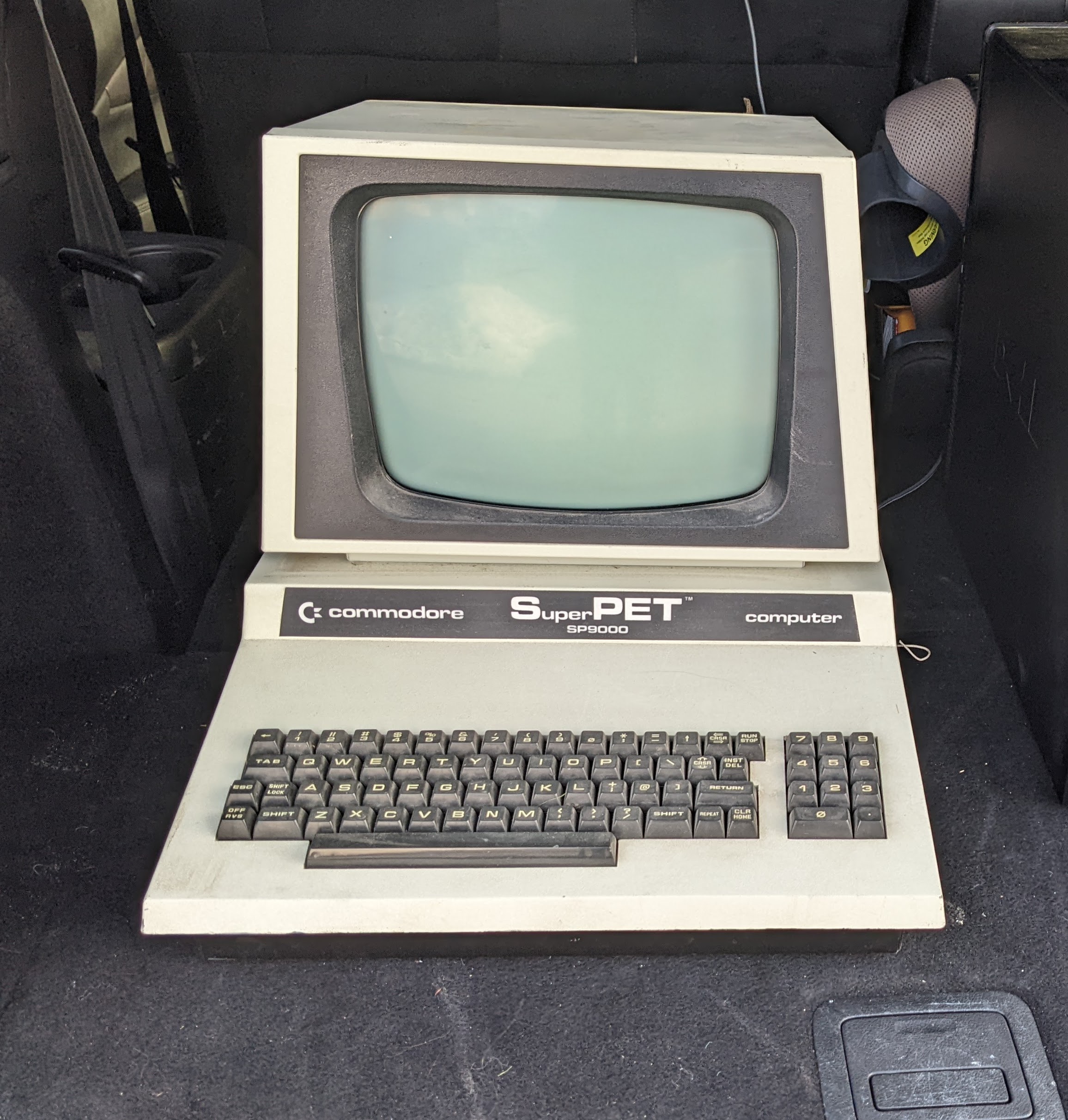
I purchased this SuperPET SP9000 in the above condition in a known not-working state. I powered it on and heard the transformer hum, but there was no output from the display, no startup chirp, no sign of life. I attempted playing with the switches on the side to enter 6502 or 6809 mode, but no changes occurred, and I couldn’t tell if it was the board or the monitor. For my initial checks, I tested for AC voltages from the transformer, verified they were coming through the connector, and then checked 5v at the CPU, CRTC, and RAM. All of that seemed just fine, it just wasn’t doing anything. As the SuperPET is effectively an 8032 with a daughterboard containing 64k of RAM, the 6502, the 6809, and supporting hardware, it seemed easier to me to make this an 8032 and debug that side first. The 6809 daughterboard was pulled off, and the original 6502 was placed in the original socket on the primary board. I checked the chip selects of the ROMs, and it appeared to not be leaving the kernel ROM at all. Seeing that there are also 12v, 9v, and -5v rails on the board, I checked the -5v and 12v at the RAM, and saw -6.5v and 10v. Probably not good, but also not sure if I had a power source problem or something wasn’t initialized properly.
Given my complete lack of experience with this era, I took this as an opportunity to try out bitfixer’s ROMulator, and ordered one. The ROMulator is a neat device that accepts a 6502 processor, but takes over regions of the memory map. This allows you to swap out entire ROMs for debugging purposes or to try out different code. It can also replace the existing RAM, or extend it. It looked like an incredible tool for repair and debugging, but could also allow me to swap out ROMs down the road without having to desolder existing ROMs. I picked up order #9000 which I thought was a good sign that this was the right move, and it took about a month to arrive.

When the ROMulator arrived, it didn’t take long to assemble it. I ordered mine with the independent programming board, which allows one to flash firmware and debug a live system without the use of an additional Raspberry Pi. The Pi is hard to find inexpensively right now, and my only spare is a Pi 1, having the shorter, non-standard header. It was easy to solder, everything that needed to be done was through-hole, so within about 20 minutes, I was ready to rock. I inserted the ROMulator into the 6502 socket, inserted the 6502 on top of the ROMulator, and set the DIP switches to emulate an 80-column CRTC PET with 32K of RAM. I flipped the switch, heard the startup chirp, and the display lit up with the familiar 31743 bytes free.

The fun thing with the ROMulator is that you can configure each memory region independently. If you only want to replace one ROM, for instance, you just redirect that region of memory to a binary file. In my case, I used it to try to determine if I had a RAM problem, a ROM problem, or both. I started out by flipping only the RAM region to the ROMulator, and allowing the original ROMs to passthrough. I restarted the machine, and I got a chirp and the boot screen — signs point to the ROMs being okay. Then, I tried the reverse, letting the ROMulator handle the ROMs and passing through the RAM. Flipped the switch, and nothing.
Neat, it’s RAM access.
My first thought was that it wasn’t actually the RAM itself — a lot of 8 bit machines from this era will boot with some bad RAM and just fail miserably at doing anything, so I felt like I was dealing with a buffer or some other logic chip. With the oscilloscope, I started looking at address lines from the CPU to the various buffers, and then from the buffers to the RAM chips, and I was getting activity.

OK. Let’s start over with the basics, and check voltages. Remember back when I saw 10v on the 12v rail? Sure enough, it’s still 10v at the RAM chips. Following it back to the 12v regulator at VR2, it was still around 10v. The -5v rail was still -6.5v, but that regulator is fed by the 12v rail, so I figured I could attack this one at a time. Removing VR2 was a pain. The 7812CK is a TO-3 package, sitting on top of a large heat sink shared with one other voltage regulator. The poles are soldered in like one would expect, but Commodore riveted the regulator to the board. I tried using a punch tool to knock them out, to no avail, and ended up using progressively larger drill bits until the regulator came loose. Did not enjoy, at all. Once out, I noticed that there’s no barrier between the bottom of the regulator and the heatsink it’s attached to, so life got less expensive. My local electronics store carried both regulators, so I picked them up. I then reattached the new regulator, and used screws and nuts to secure it to the board and heat sink.
Now there was a nice, clean 12v. The -5v regulator at VR1? Still -6.5v. Doh.
I’m not sure what happened to this machine that two voltage regulators decided to give up, but that’s in the past. I’m glad I picked up both regulators, and luckily, VR1 was a lot easier to replace. It’s a LM7905CT in a TO-220 package with three through hole pins going into the board, and no other carrier or heat sink. A quick desolder of the three pins, insert the new one, solder it and bend it back to a reasonable angle. I applied power to the machine, but still no startup chirp. The voltages at the RAM chips, however, looked great.
Now what?
I went back to the ROMulator and continued messing around with RAM a bit. Instead of having the RAM completely pass through, I started dialing down the passthrough so that the ROMulator would handle some of the RAM available, but let the rest of it pass through. If I had the ROMulator handle $0000-$0400, I could get the PET to boot with less than 4kb free, but it absolutely would not do anything useful. The ROMulator also had pettester available to do memory checks and other diagnostics. It would start up just fine, but once it got to the memory test, the screen would start filling every other character with the @ symbol. Turns out, that’s hex 00, and I started to assume that there was some sort of addressing problem. I started looking at the address lines starting at the CPU all the way to the RAM, and noticed that some of the readings coming out of the 74LS393 at UD13 toward the RAM looked off. I connected a logic analyzer to the inputs and outputs and realized that it wasn’t quite lining up during the initial memory test. I piggybacked another 74LS393 on it, and the symptoms changed significantly, where more RAM would be detected, and that was the final straw. Out came the original 74LS393, and replaced with a new one.
With the ROMulator still keeping the first 1k of RAM internally, it was now detecting slightly more RAM, but still not working properly. The big difference now was that pettester no longer crashed hard, but actually declared some memory failures. We probably actually have RAM faults at this point, likely not helped by bad voltages and age. At this point, I ended up using a trick from Adrian’s Digital Basement to find the bad RAM. I entered the following BASIC program:
10 for i=1 to 4096:poke 1280+i,82:next iI’d then use SYS 4 to enter the machine language monitor, and looked at the memory from $0400-0440 (m 0400,0440), which represented the BASIC program I just entered. I exited back to BASIC and ran the program until it ate itself, which was quickly, and then redisplayed that memory range. Comparing the two outputs, it became clear when converting hex to binary which bit was sticking, which was the first one, corresponding to data line D0, which means the 4116 at UA19. Out it came, in went a socket and a new 4116. Once I confirmed it started up, I yanked out the ROMulator to see where we were at.

Ayyyyy.
Okay, sure it’s the wrong amount of RAM, but that’s a success no matter how you look at it. Since it was a problem with the upper bank of RAM, I had to change methods just a little bit. I started by looking at the other 74LS393, but that all looked just fine. On startup, the PET will do a memory test to determine the upper bound, and all of the signals looked normal. I then tried a variant of the above BASIC program. Since we were no longer overwriting BASIC memory, I had it start in the upper bank, and just had it read back values after poking them, to see if 82 turned into something else.
10 for i=1 to 4096:poke 16383+i,82:print peek(16383+i) " ";:next iThis time, we ended up at the opposite end with D7 giving trouble. Out came the 4116 at UA4, socketed, and a new one put into place.

Hello.
At this point, I could finally start writing BASIC commands and getting the proper response, including loading programs from a SD2PET Future. Pretty satisfied with the result, I reattached the 6809 daughterboard and the side switches to see what might be broken there.

Turns out, nothing.
From here, it’s time to play around a little bit. To come in the future will be a better cleanup of the case, and at some point in the future, the Super OS/9 MMU will arrive from RETRO Innovations, and I can give OS/9 a go on the 6809 side of this SuperPET. I may also have a very broken Commodore SFD-1001 heading my way, so I might have an option for using actual disks in the near future.