The Ongoing Saga of this Commodore B128 (1/4)
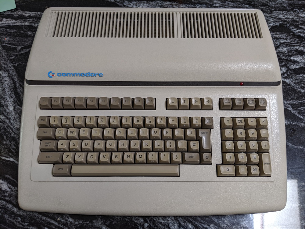
This is my Commodore B128, serial C002720. The B128 is the low-profile US version of the Commodore CBM-II, a machine designed to replace the PET/CBM series, released around the same time as the Commodore 64. Other pages, linked below, do a great job covering the history of this machine.
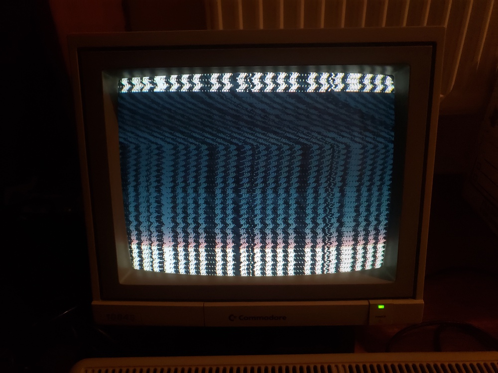
When I received it, it looked great but did not work. Upon applying power, the LED lights, but the connected screen over composite is garbled, looking almost like it lost sync. On a 1084S, presents almost looking like characters. On a LCD over composite, just looks like flickering.
No sounds are made when power is applied. Pressing CONTROL-G on the keyboard does not produce a beep. As a side project, connected the keyboard via USB to another machine, and verified that the keyboard works splendidly. Connecting a Commodore 4040 drive to the IEEE-488 bus will light up when the B128 is booted, but that could just be power applied to the bus. Attempting to type commands does not result in any activity from the drive.
After a little bit of starting, I decided to remove the variable of potential ripple or power shorts by recapping the OEM power supply. There are plenty of forum posts of DOA power supplies, might as well get one win in.
Resources
First up, the resource list. None of this diagnosis would be possible without the following pages, created with obvious love and care by the community of people who continue to appreciate Commodore and/or the CBM-II machines.
- B128 Schematics, manuals, and firmware at zimmers.net
- Steve J. Gray's The Commodore CBM-II Page at 6502.org
- Edward D. Shockley's Commodore B Series at insectria.org
Diagnosis
Time for some diagnosis with absolutely no knowledge of how anything this works, armed with schematics and images from zimmers.net. I'm making this post to keep myself accountable.
- Power rails
- No short to ground
- Clean 4.99v at power LED
- Clean 4.96v-5.02v on major ICs across the board
- Addressing, timing, reset
- CPU clock is clean
- Dot clock is clean
- RESET line starts low, then moves high, and the address lines start to make some noise, so it seems like the 6509 might be ok
- Address lines have continuity throughout
- Address lines out of 6509 at U9 look like decent square waves showing proper TTL. Each look okay on the oscilloscope, but A13-A15 on the logic analyzer look stuck high after a short amount of time -- maybe after the RAM test?
- Some research here suggests my kernal ROM isn't in a good place
- Traced video lines from plug, through TTLs back to the 68B45P at U7
- Continuity is good across each path
- Video signal looks something approaching normal
- In most, but not all, cases, there is no hsync signal out of the 6845
- In some cases, there is an hsync pulse, with no relevant change in output
- It seems that the 6845 isn't going to initialize on its own, the CPU needs to initialize the 6845, which also sets sync
- ROMs
- Signals out of kernal ROM at U61 look fine, from a TTL perspective
- For a fleeting moment, having the BASIC HI ROM at U60 inserted would cause a very noisy looking data bus, leading to a wild goose chase that I couldn't reproduce later
- Forums seem to indicate having a kernal without basic lo or hi would boot into a monitor, but no change when leaving those out
- Building a 2364 to 2764 adapter and testing in a TL866-II show that each socketed ROM content matches the binaries available online
- Buying a 2764 to 2364 adapter, burning a ROM to a 27C64, and inserting does not change anything for any of kernal, basic lo, or basic hi. I did not try all three at the same time, but I have no reason to believe that it warrants further checking
- Chip select coming from a 74S138N at U40 looks high on kernal (U40p7), basic hi (U40p10), and basic lo (U40p11), and that also seems super suspect. Chip select comes out of a 74S138 at U40, which is soldered. Could be bad? Can't test until desoldered, but maybe this is a RAM issue
- RAM
- Initial checks of the data in/out lines (which are bridged) show that U65 and U73 kinda look shorted to ground on the oscilloscope, certainly a lower frequency on the logic probe
- For a brief moment, every single data line looked weird, but that could be the 275 doing its job, or the 275 sucks
- Tracing back to a 74LS275 at U12 shows the same grounded line. The opposite side of the 275 looks normal, so either the 74LS275 has a short, or something else on D1 has a short
- D1 comes from U12p12
- Passes through U65, U73, and the other bank of RAM if populated
- Passes through P9p4
- No obvious issues on the top or bottom of P9
- Maybe a RAM IC is dead?
I'm at the point now where it's time to desolder parts. I'm likely starting with the 74LS275, and if that ends up good, moving on to the two RAM chips, and then looping back around to the 74S138.
I also have a standing offer to test the rest of my socketed chips in a working B128, and if this desoldering doesn't go well, that's my next step.